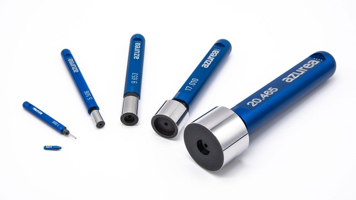
A plug gauge measures nothing. It gives you no dimension, no figure, no value to write on a report. It answers one question, yes or no: is your part on the right side of the limit? That is precisely why it is faster and more reliable than a micrometer.
Provided you know which limit it checks, and why two gauges are needed where one instrument would seem to do.

Two gauges, two different questions
The practical consequence is simple. If the GO end passes and the NO GO end is stopped, the part is good. If both pass, the bore is oversize. If neither passes, it is undersize. No reading, no interpretation, no possible error.
It also explains why the GO end must have the full form and full length of the bore. A slightly oval or barrelled bore can give the right dimension at two points and still refuse a complete cylinder. A micrometer does not see that.
Reading an ISO 286 dimension
A drawing almost never says "10 mm bore". It says Ø10 H7. That notation carries three separate pieces of information.
On a shaft the same grammar is written in lower case. A Ø10 g6 falls between 9.986 and 9.995 mm, entirely below the nominal size, which guarantees clearance with an H7 bore. That is the classic sliding fit.
The same tolerance is not the same dimension
Here is the point many people discover late. An IT7 is not a value, it is a grade of precision relative to the diameter. The larger the part, the wider the interval, because machining large is inherently less precise.
The ten per cent rule
A gauge is itself a machined part, and therefore has a tolerance. Established practice gives the gauge ten per cent of the part tolerance, split between the two ends. And that share is taken from inside the zone, never outside it.
A second allowance applies to the GO end alone: the wear allowance, of the order of a tenth of the gauge tolerance. The GO end rubs at every check and loses material, and therefore diameter. The allowance is added in the direction opposite to that wear, so the gauge stays correct for longer. Below a part tolerance of roughly 0.09 mm it becomes negligible and is no longer applied.

Choosing from the catalogue
Four decisions, in this order.
| Decision | The options | What settles it |
|---|---|---|
| Progression | 0.001 mm or 0.01 mm | A 1 µm step is only justified if your tolerance falls below 10 µm. Otherwise it is a more expensive set for a resolution you cannot use |
| Material | Steel or hard metal | Hard metal for series inspection, where wear on the GO end becomes the limiting factor. Steel for occasional use |
| Handle | With or without | The handle keeps your hand off the gauge and so limits expansion. Without a handle for mounting in a fixture |
| Pin gauge length | 15 mm or 32 mm | 32 mm to reach the bottom of a bore or pass through a thickness. 15 mm where access is clear and rigidity matters |
Two families sit side by side at Azurea. The sets with a regular progression, where each gauge is a nominal diameter, are for measuring and fine sorting. The ISO plug gauges are toleranced directly to a class from the drawing, and are therefore ready to check an H7 with no calculation. The Cary ring gauges cover external inspection, in steel or hard metal.
What throws an inspection off
Temperature first. All standardised dimensions apply at 20 °C. Steel expands by about 11 µm per metre per degree, which is 0.11 µm on a 10 mm bore for one degree of deviation. Nothing at all. But a gauge held in a full hand rises by about ten degrees, and those 1.1 µm change status depending on the tolerance being checked.
Force next. The GO end must enter under its own weight, without you pushing. Forcing turns an attribute check into a subjective judgement, and lets out-of-tolerance parts through.
Wear last. A GO end thins with use and ends up accepting bores that are too small. There is no visible sign: only periodic inspection of the gauge itself reveals it. That is the reason for the wear allowance, and the reason a set of gauges has a functional expiry date even when it looks new.
In short
A micrometer gives you a dimension and leaves you to judge. A limit gauge leaves you nothing to judge, and that is exactly what is asked of it on a production run. The two are complementary: the micrometer to understand a drift, the gauge to sort without thinking.
Which leaves the rule that sums up all the rest. Choose the gauge from the tolerance on the drawing, never from the nominal size. The tolerance is what decides the progression, the material and whether you need an ISO version.
So, gauges or instruments on your production runs? Tell us in the comments.
Tolerance values per ISO 286-1:2010, system of limits and fits. The GO and NO GO principle follows Taylor's principle, carried over into the ISO 1938 series on limit gauges. Product characteristics per the Azurea and Cary catalogues. All standardised dimensions refer to a temperature of 20 °C.